REM-B Hydraulics and CG Power Systems Belgium develop a test-unit “fatigue” testing of transformers.
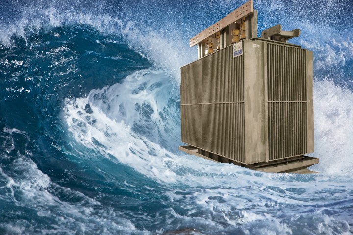
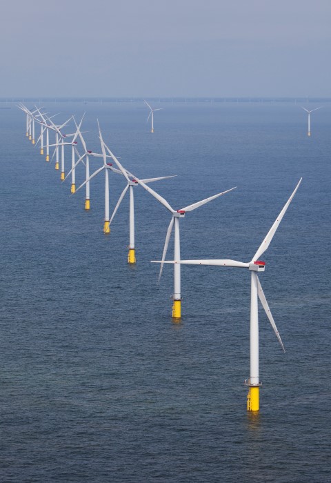
Initiatives like ‘Europe 2020’ (which targets 20% renewable energy in the overall energy supply by 2020) and a growing ecological consciousness induce an ever-increasing demand for renewable energy. Sustainable resources in Europe are predominantly produced by wind turbines. The wind that propels these turbines is steadier and more powerful in the open stretches that are indicative of the ocean along the European coastlines. Therefore new wind turbines are almost always constructed on sandy shoals in the sea. Due to the higher intensity of the wind, the ability of these offshore turbines has grown enormously in recent years and it is expected that the capacity will keep on expanding.
The transformers installed in these offshore turbines are exposed to interchanging stress and fluctuating temperatures in the transformer body. These two circumstances cause the electrical isolating coolant in this type of fluid-driven transformer to alternate between heating up and cooling down. As a result of these changes in temperature the fluid will dilate and then constrict, putting stress on the transformer housing and causing mechanical fatigue. To prevent “fatigue” in these kind of offshore turbines, the transformers and their housings are subjected to an extensive array of tests before installation.
Our state-of-the-art test stand will regulate the fluid capacity and the corresponding pressure inside the transformer by pumping fluid in and out of the transformer housing. By intelligently controlling the pumps in a destructive life cycle test, we can simulate the mechanical fatigue the transformer housing will sustain while being operational. These tests will be customarily carried out on prototypes.
Our test stand is also outfitted for non-destructive test programs, which will allow us to perform a quality control on the transformer housings before use in the wind turbines. These tests, where the volume and the pressure inside the system will function as variable parameters, will permit us to establish a flexibility curve. This curve will disclose how the transformer reacts to various conditions. Based on this information you can tell if the transformer housings measures up to the requirements or not.
From the flexibility curve you can also derive the maximum allowed amount of pressure inside the housing During this test the amount of pressure is increased step by step until the transformer housing starts to deform plastically. This point determines the maximum amount of pressure allowed for standard operations in the transformer. This test is executed without damaging the housing whatsoever and can be utilized to inspect the housing quality before it is repleted with the core, windings and liquid dielectric.
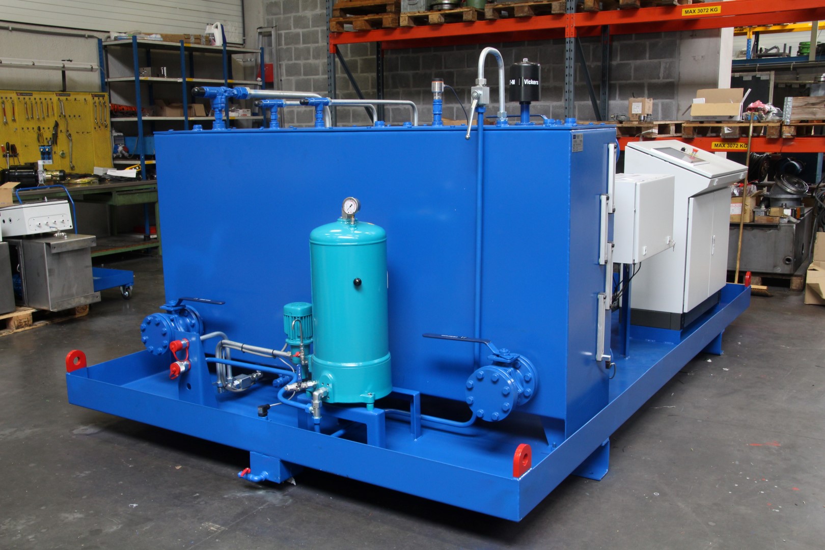
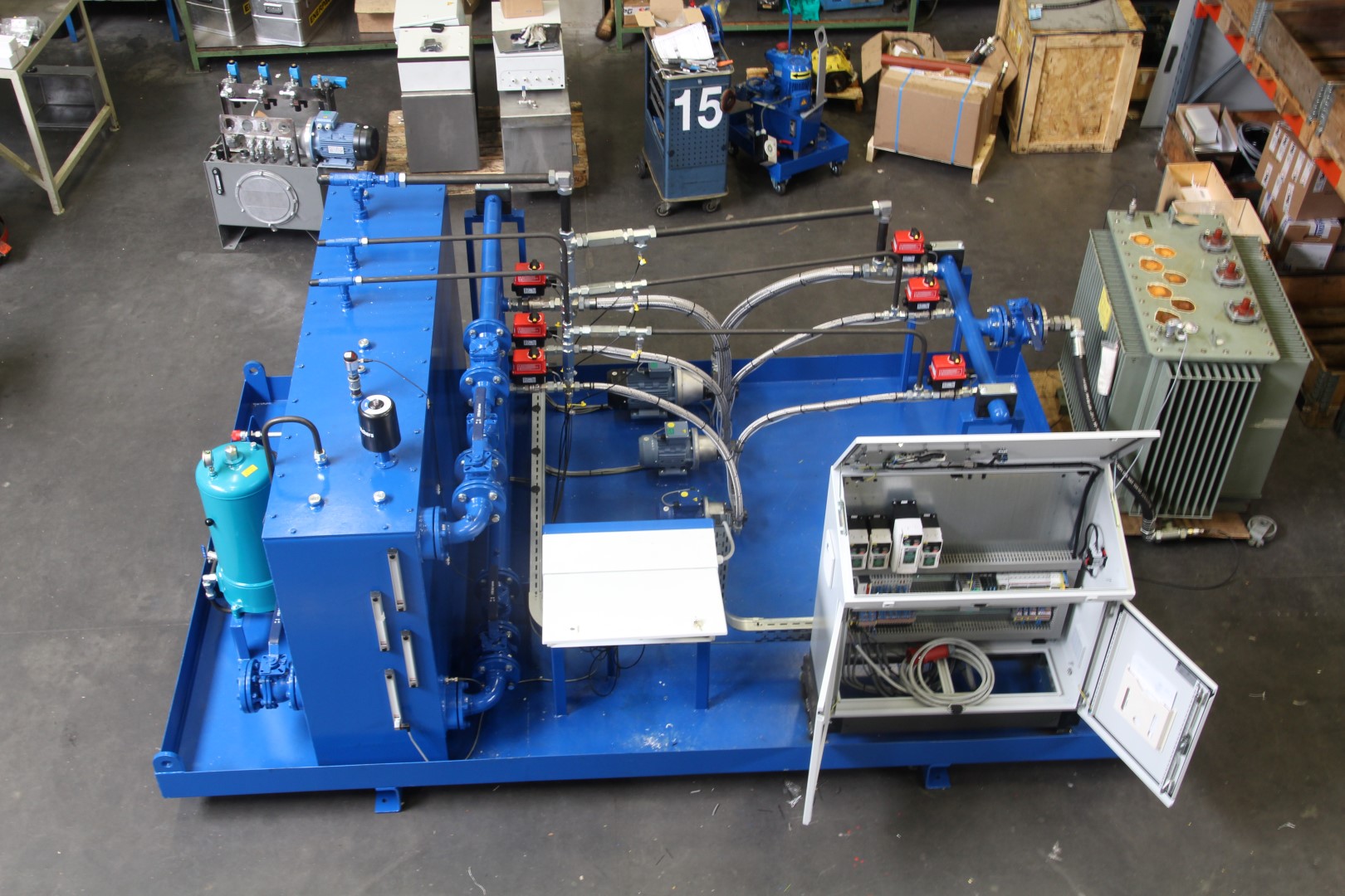
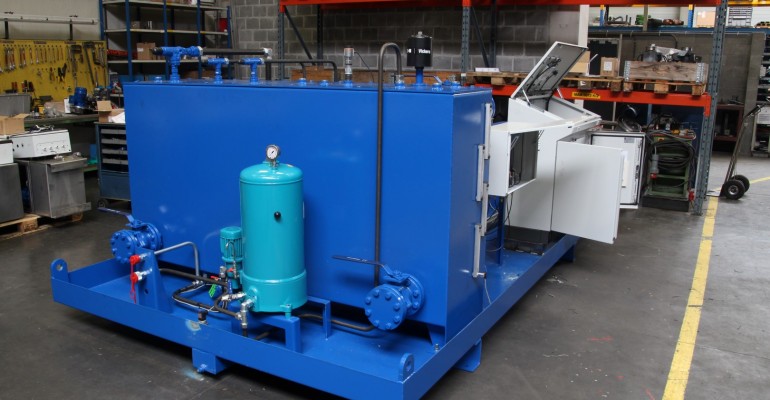
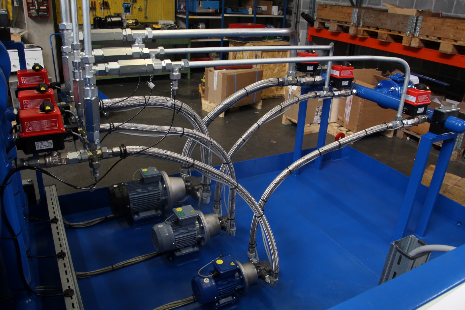
Our installation consists of 4 crucial elements: the driving mechanism (composed of 3 pump motor systems), the oil management system, a network of intelligent sensors and a control center from where the installation is managed.
The displacement and pressure are regulated by 3 frequency-driven pump motor systems. We have opted for fixed displacement hydraulic gear pumps. These pumps are equipped with specific seals and is immune to the aggressive isolating coolant pumped throughout the system. The variable flow rate of the installation has a vast range of 60l/h to 600l/h. This substantial range allows us to test the entire scale of CG production, from small distribution transformers on the side of the road to bigger power transformers in electrical plants.
The system is manufactured for usage with four different types of fluid who are habitually used as a transformer medium. The variable pressure is controlled by intelligently guiding the motor frequency and the electronically driven ball valves. The pressure in the transformer will vary between 300 millibars (underpressure) to +500 millibars (overpressure) during testing. The pressure differences coincide with the pressure differences caused by temperature fluctuation and stress on an operational transformer during extreme weather conditions.
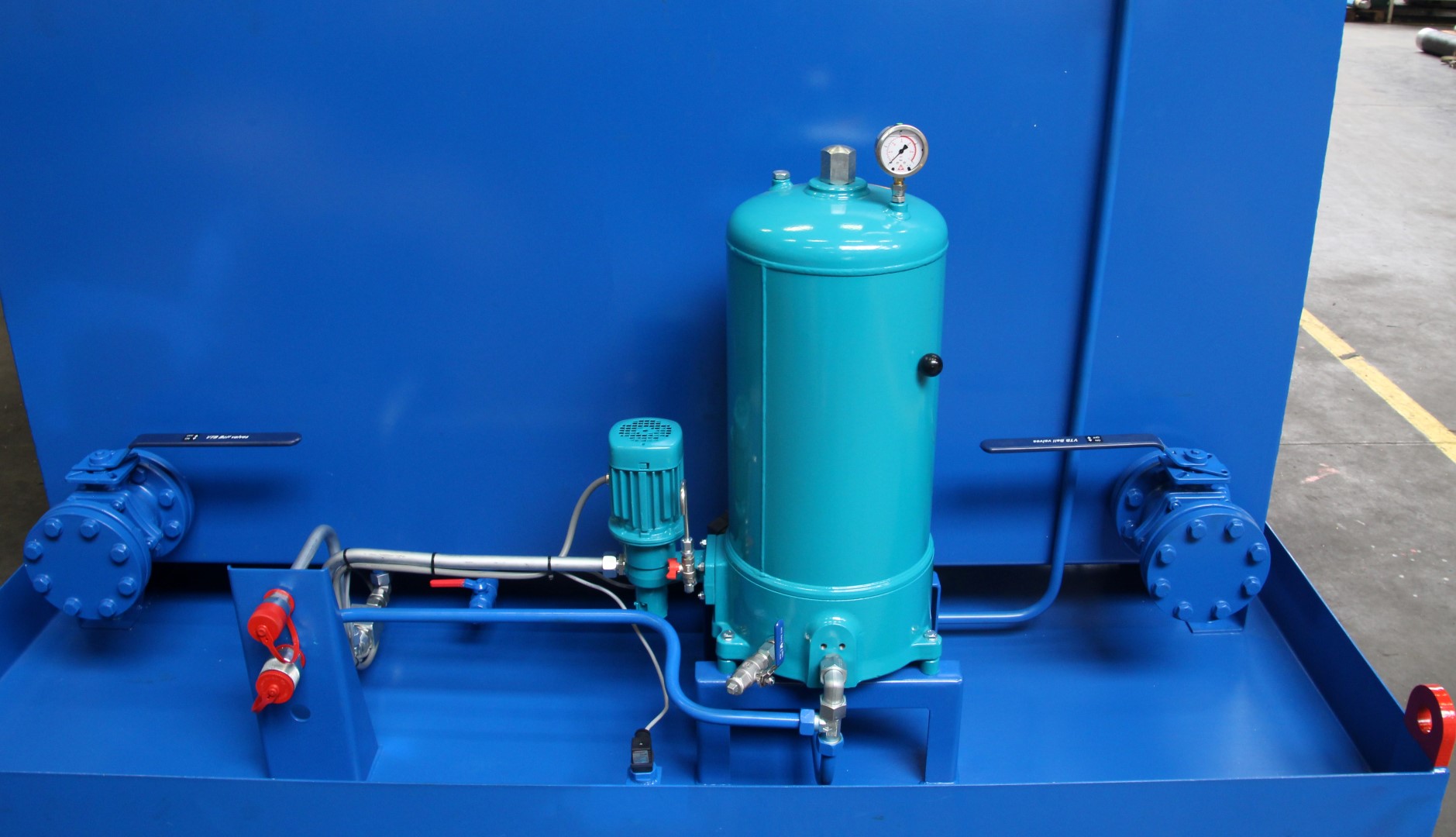
Our testing infrastructure nor the old/new transformers that are being subjected will not be damaged in any way during the tests. Therefore the test should always be performed with clean hydraulic fluid. To prevent corrosion or damage by the use of contaminated oil, we have implemented a high quality filtering system with Bypass Air filtration. The filtering system contains a special filter which is capable of draining the contaminated particles out of the used liquid. It also contains a dewatering installation. Water is not welcome, not only because it will cause rust in the hydraulic system but also because of the conductive nature of water. It’s unnecessary to say that water does not belong in a transformer.
A network of built-in sensors is responsible for control and safety. The amount of pressure is safeguarded by a couple of pressure sensors. The temperature of the fluid inside the transformer and the oil reservoir are under the control of temperature sensors. There are also 2 level-measuring sensors implemented inside the system to measure the level of the fluid in the reservoir and inside the transformer. This will obstruct the hydraulic pumps from sucking in air. This setup will also permit us to discover leaks in the transformer.
The entire test unit is controlled by an electrical drive circuit with touch screen, making it easy to calibrate the parameters.
Flexibility and expandability were the key words during the design of this test installation. This way we are able to expand the amount of volume the installation can pump in the near future. Transformers in offshore application are constantly getting bigger and performing similar tests on transformers on offshore substations and drilling rigs is already a necessity today. Furthermore the provided input channels for the sensors and the programming of the installation are adaptable to future needs,
This installation was produced in july 2015 by REM-B and will be fully operational in the Mechelen branch of CG Power Systems right after the summer holidays.